On this page I've gone though the steps I took to wire the motors up to a motor driver and then connect that up to the RPi. These changes are destructive, so once started it will be hard to go back to original setup!
Note: You can click on the images for a larger view
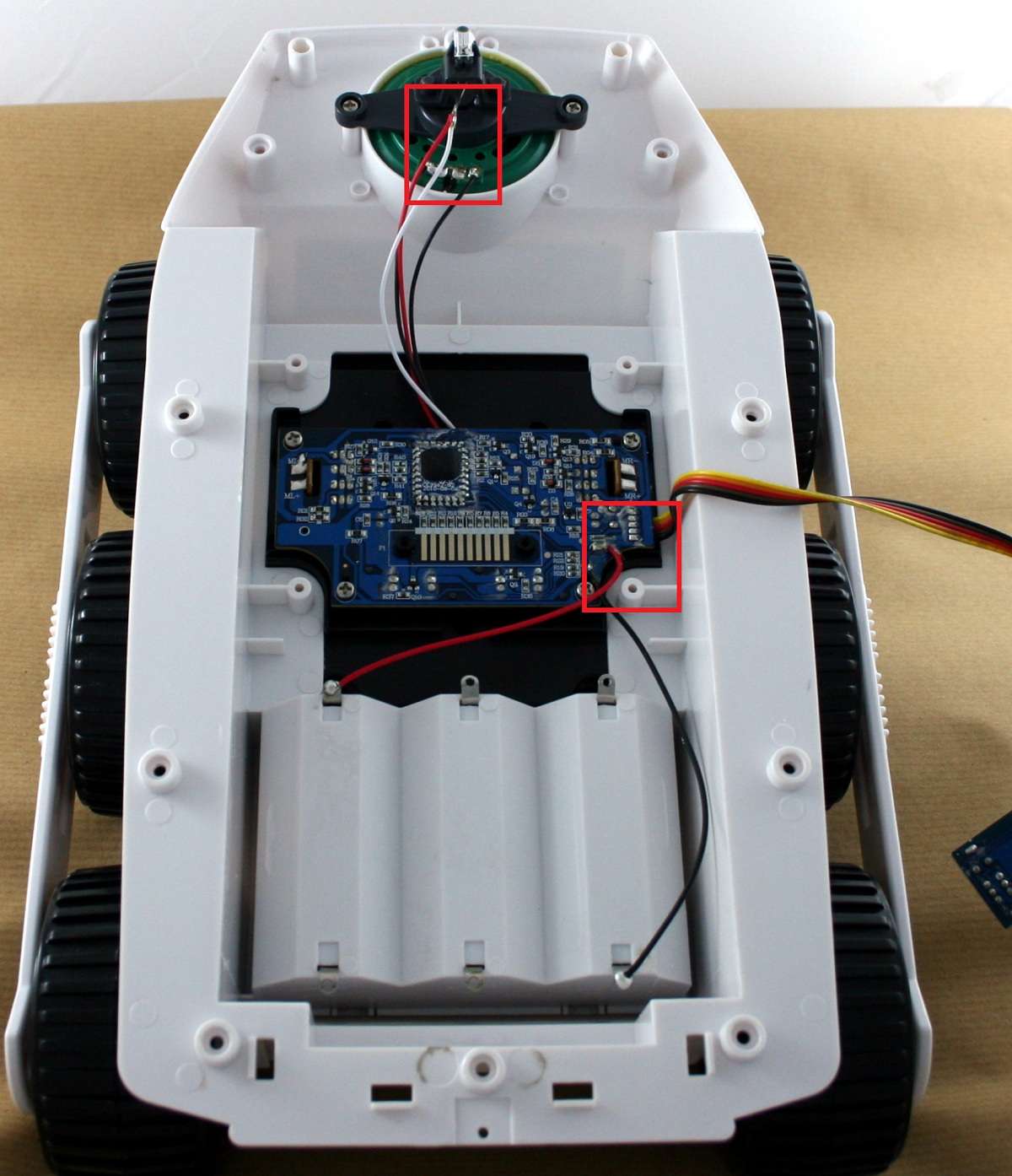
| Cut the wires leading to the main PCB. The ones for the switch and power should be cut close to the PCB (so we can re-use them later) whereas the ones to the the LED and speaker can be cut where-ever. |
 |
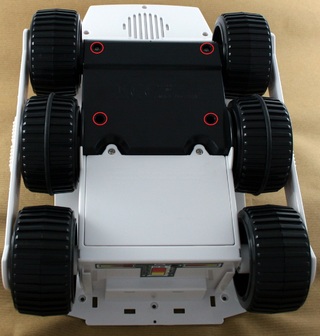
| Turn the BigTrak upside down and remove the four screws holding the motor assembly in place (This will reduce the chance of soldering iron damage to the main body). Carefully turn the BigTrak back over and lift it up until the drive unit slips free. |
 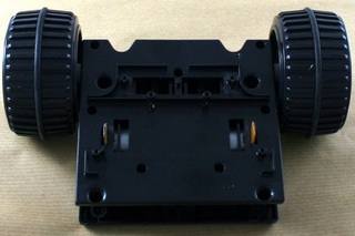 |
Remove the solder connecting the PCB to the motors (I used solder mop to do this) and then remove the PCB.
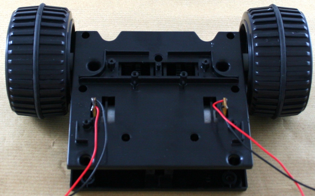
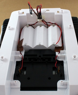
With the PCB removed we can now attach wires to the motors to drive them from the Raspberry Pi. The wires will need to be long enough to reach the back of the BigTrak, its probably best to have them extra long as they can be trimmed to size later. |
 |
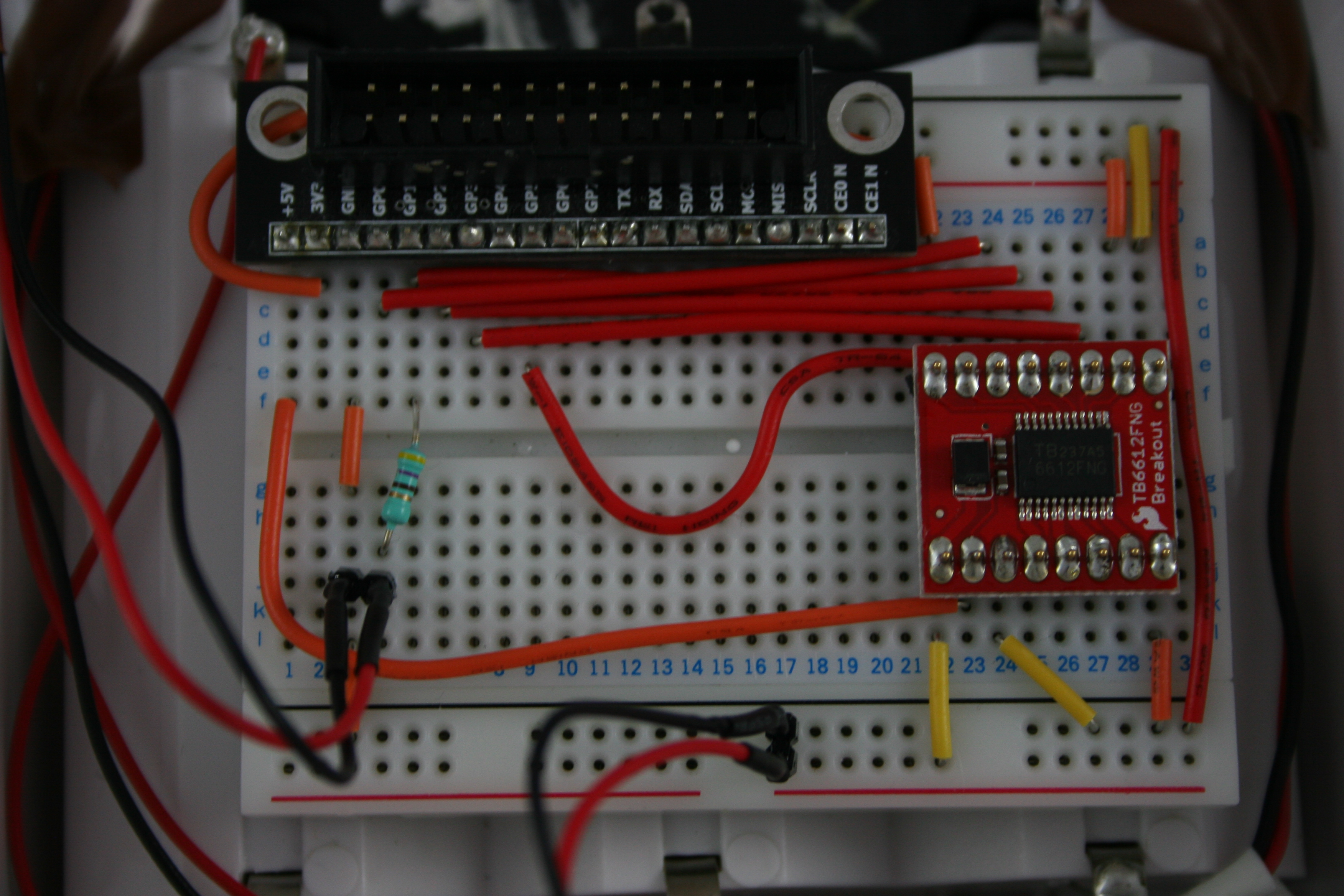
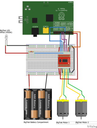
With the motor's back in place we now need to build up a circuit to drive it from the Raspberry Pi. For my BigTrak I've used a Ribbon Cable to connect the GPIO pins on the RPi to a BreadBoard, before connecting it up to a Dual Motor Driver (TB6612FNG) to actually drive the motors (This keeps the higher voltage the motors require away from the sensitive Raspberry Pi inputs)
The connections I've made are (For no particular reason)
| RPi GPIO | Motor Controller |
| 24 | AIN2 |
| 17 | AIN1 |
| 18 | STBY |
| 21 | BIN1 |
| 22 | BIN2 |
With the PWMA and PWMB pins directly connected to the 3.3V power rail to ensure that the motors will run at full speed
when turned on.
|
 |
| The Breadboard is going to be installed on top of the battery compartment inside the BigTrak, so the wires from the motors can be brought to the back to the unit and cable tied into place. The wires to the batteries can also be brought back to the same place to keep things tidy. Depending on where you cut the battery wires you may want to replace them with longer leads.
To easily connect the motors and batteries to the BreadBoard I soldered some modular connector plugs to the ends of the cable, allowing them to just push into place. (These are code DC18U at Maplins in the UK) |
 |
| Position the BreadBoard on top of the battery compartment (sticking it into place if you prefer) and connect the motors and power to it. Optionally you can attach wires to the LED and also connect it to the Breadboard , I've done this in the picture and connected it to the same connection as the "standby" pin (Using a 470Ω resistor to make sure it doesn't pull too much current) so the LED lights up when ever the motors are active. |
 |
| Assuming you've used the same components I have then with everything wired up the connections should match those in this breadboard layout image. If you have a slightly different variant of the motor driver then you will need to check its datasheet to determine how its layout differs and adjust the breadboard layout accordingly. |
 |
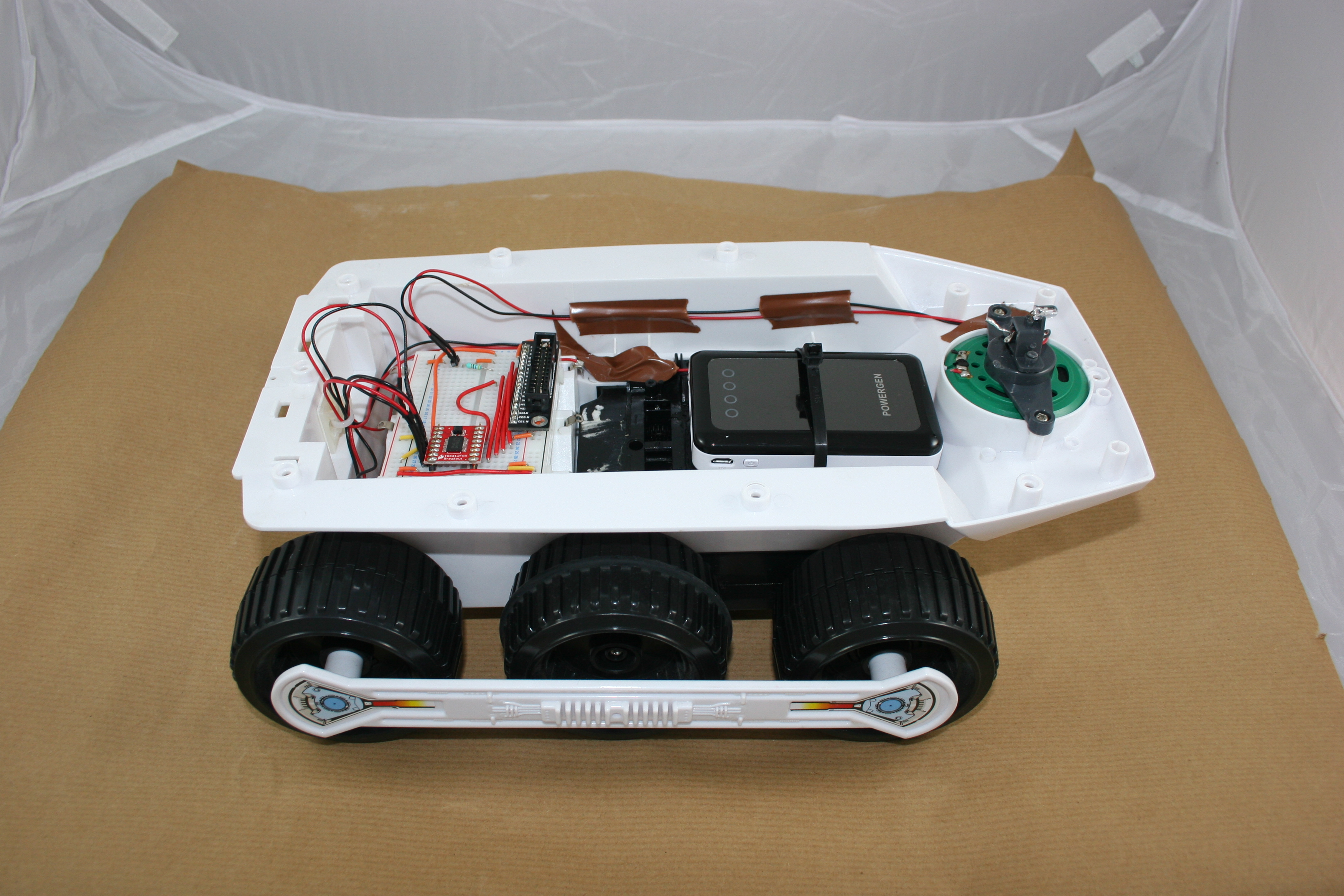
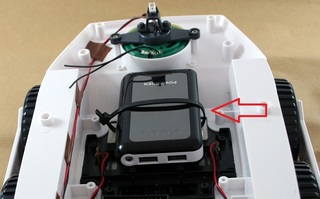
| To power the Raspberry Pi itself I next installed a battery pack with USB ports on it above the motors. This type of battery is typically sold as a portable mobile phone or iPad charger. The one I'm using is around 8000maH and can run the Raspberry Pi for up to 8 hours, depending on what USB devices you have plugged into it.
To hold the battery in place I've used a couple of sticky pads and a cable tie. |
 |
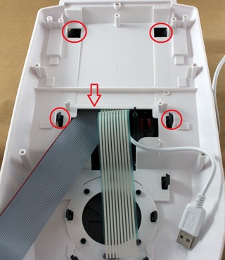
| As the Raspberry Pi is going to be mounted on the top of the BigTrak we need to run the ribbon and power cable through the top of the case. To do this turn the top of the BigTrak upside down and release the front two catches that hold the dark grey plastic in place, this will give you a big enough gap to feed the ribbon cable and USB power cable through. Make sure that the red edge of the ribbon cable correctly matches up with the connector on the BreadBoard so you don't have to twist the cable inside the case. |
 |
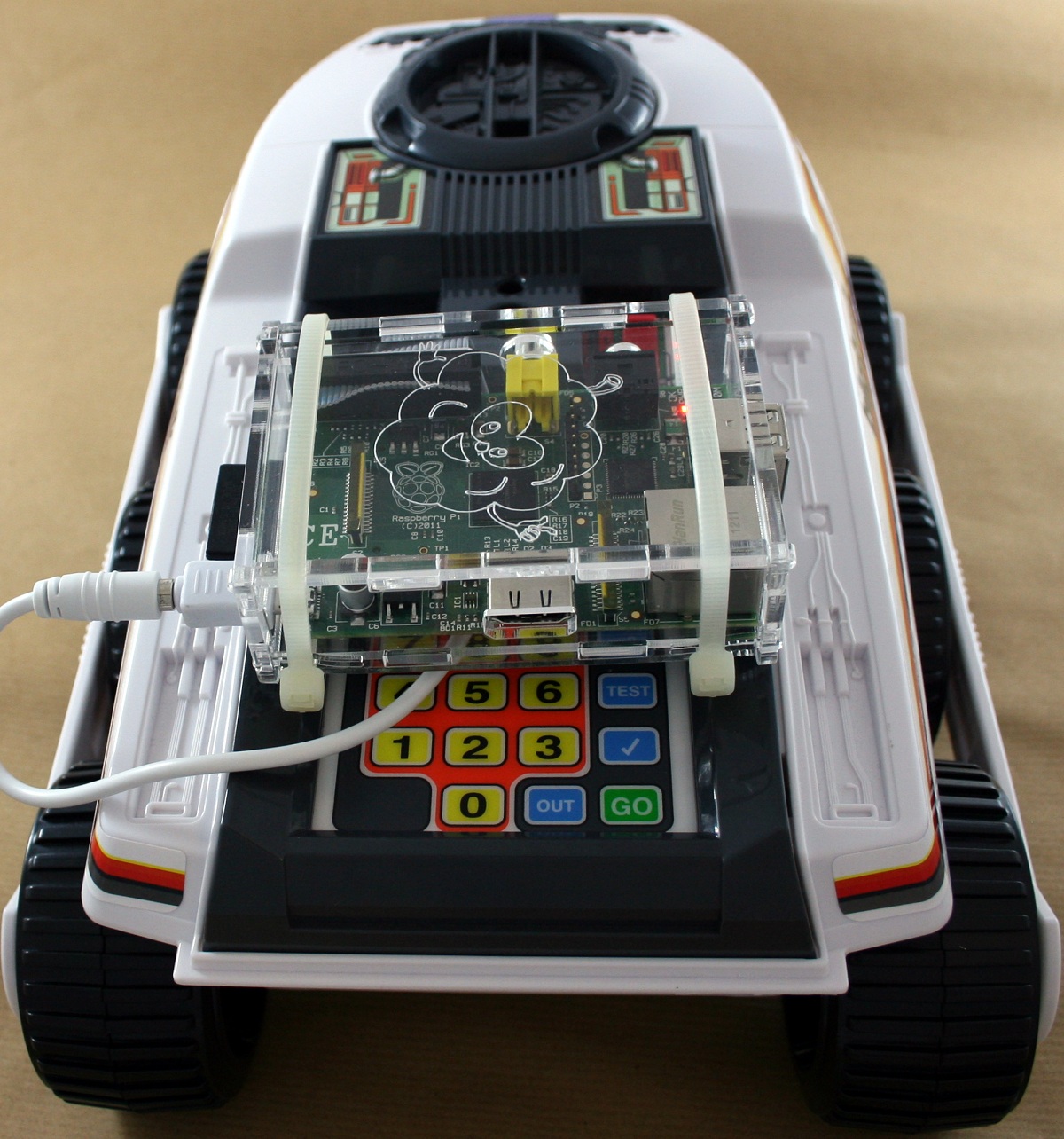
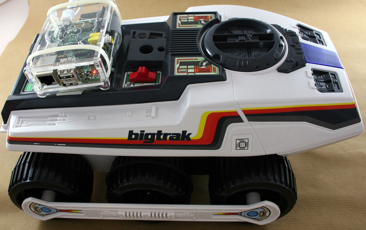
| Put the top of the BigTrak back on and mount the Raspberry Pi on top of it, keeping the GPIO pins towards the front to allow the ribbon cable to easily connect. Again I've just used some sticky pads and cable ties to hold the Raspberry Pi in place. You can just attach the bare PCB to the top of the BigTrak, however this can cause the SD card to press against the edge of the BigTrak and bend, so I've gotten a case to protected the Raspberry Pi. |
 |
| Connect up the Ribbon cable and power cable to your Raspberry Pi and it should boot up, ready to be told what to do.. |
 |